Introduction
Two-dimensional technical drawings have been essential in engineering since the 1300s, when perspective drawing was invented. These drawings initially depicted real objects, and later advancements in descriptive geometry and orthographic projection further developed engineers' ability to visually represent ideas. Until the introduction of 3D CAD modeling in the 1980s, engineers primarily used 2D technical drawings to document designs.
Creating a Technical Print From Scratch
Clear and precise technical drawings are essential in manufacturing, as they dictate every machining step and critical feature. Ambiguities in drawings can lead to costly errors and project delays.
Many machine shops reject poorly drafted jobs with missing dimensions, unclear designs, or insufficient details. When working with a manufacturing shop aggregator like Accurate Machine Products, unclear drawings often require extensive revisions.
Engineers should strive to create accurate manufacturing drawings from the outset to minimize redraws and revisions. Here's a best-practices guide for creating professional and comprehensive manufacturing drawings, whether in 2D drafting or converting from 3D models.
Create a Template
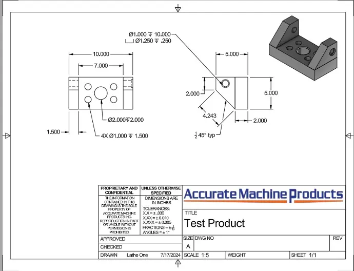
Create a unified template suitable for both detail and assembly drawings adhering to ASME or ISO standards (depending on location). Include a title block positioned in the bottom right corner containing company or organization details, names of personnel responsible (designer, checker, approver), drawing title, revision reference, sheet size, view alignment conventions, and primary scale.
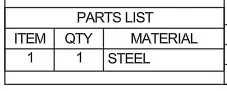
Ensure the title block includes a section for default tolerances not shown alongside dimensions on the drawing. Above the title block, include a parts list detailing any additional components required for assembly, referencing each part to the drawing by its title or page number.
2. Check Your Scale and Units
Make sure the drawings are properly scaled to fit the page, ensuring clear visibility of dimensions in each view. If sending the part for manufacturing internationally, it's advisable to use the metric system for dimensions. When uncertain, employing a dual-dimension layout with both sets of measurements is recommended.
3. Ensure Correct Tolerances
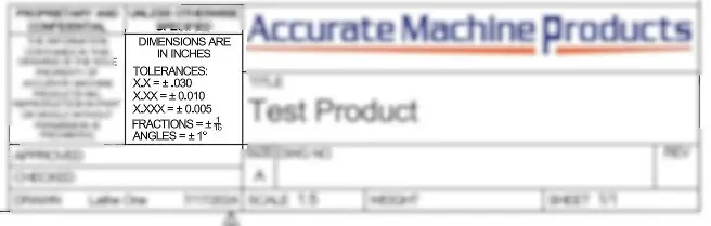
It is generally advisable to select appropriate tolerances for modern CNC machines, typically around +/- 0.005 inches for distance dimensions. Accurate Machine Products outlines standard tolerances for various processes in its manufacturing guidelines.
Tolerances may be tailored based on part design and production method, but adhering to standard tolerances helps align design expectations and control costs. Tolerances tighter than the standard range are classified as "tight tolerances," while those broader are termed "loose tolerances."
Get Your Free Quote Today
Don't wait any longer on your project!
4. Create Templates For Subsequent Sheets
Before making revisions, establish a template featuring a continuation title block and a revision table situated in the top right corner. The revision table should include details such as the revision date, reason for the change, and the name of the person responsible for the revisions.
Additionally, ensure that both the first page and subsequent pages of the drawings clearly indicate the page number and the total number of pages, typically located in the lower right corner.
5. Ensure Views Align With The Projection View
Once drafting begins, it's crucial to adhere to the correct projection alignment specified. This orientation guides the manufacturing process, ensuring all views align with the convention detailed in the title block. In the US, third angle projection is standard, while first angle projection is more prevalent in Europe.
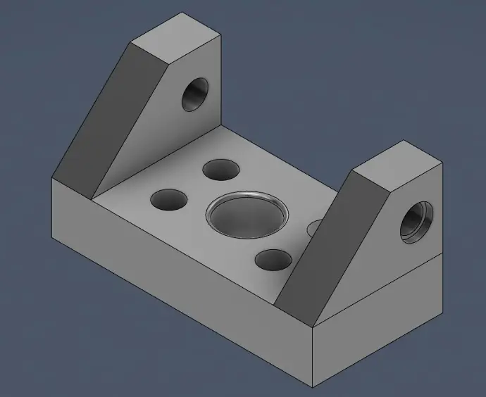
6. Include an Isometric View if Possible
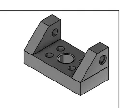
If space permits, including a 3D isometric view is beneficial for machinists during part manufacturing. These views do not require alignment with orthographic views but should be drawn from the correct corner to convey the desired orientation. Avoid adding dimensions to the isometric drawing due to its scale differences, but include relevant notes. Isometric views provide additional details about the part in three dimensions and can illustrate critical information such as installation directions for inserts or pins in assemblies.
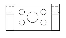
7. Limit the Number of Hidden Lines
Excessive hidden lines and tangent lines can diminish the clarity of a drawing. Include only essential hidden lines; others can be noted and highlighted in an isometric drawing or detailed in an exploded view for smaller features.
8. Ensure Clear Dimensions
Position dimensions outside the view and avoid overlapping dimension lines for clarity. Ensure no redundant dimensions appear across different views or are already implicit in the 3D model within specified tolerances. Dimension critical areas, reference dimensions, GD&T requirements, threads, and surfaces as necessary. For arcs greater than 180 degrees, specify diameter; for arcs under 180 degrees (e.g., fillets), use radius. Right-angle intersections do not need angle dimensions. Include informational dimensions in parentheses for reference, like total length derived from multiple smaller dimensions.
9. Include Full Specs for Materials and Surface Finishes
Simply stating the metal type is insufficient. Stainless Steel 304, for instance, varies with four different ASTM specifications based on its application. Specify any specific surface finishing instructions such as edge breaks and deburring clearly in the notes section of the drawing.
10. Call Out Threads with Complete Thread Specs
Specify complete thread specifications for threaded features, including thread form, series, major diameter, threads per inch, class of fit, and depth. Standard threads are recommended for ease of tooling use; for custom threads, provide a detailed view to define the thread form fully.
11. Use the Appropriate Type of Linear Tolerance
In manufacturing, engineers use tolerances to specify acceptable variation for dimensions, ensuring parts maintain form, fit, and function. Three main types of tolerances are commonly used:
1. Bilateral Tolerances: Allow variation in both positive and negative directions from the nominal dimension (e.g., ±0.005”).
2. Unilateral Tolerances: Permit variation in one direction only from the nominal dimension (e.g., +0.005” / -0.000”).
3. Limit Dimensions: Specify the largest and smallest acceptable values; any dimension between these limits is acceptable (e.g., 0.525” / 0.520”).
Bilateral tolerances are typically used for general dimensions, while unilateral tolerances and limit dimensions are employed for critical fit and tight tolerance features, ensuring clarity and readability of the drawing.
12. Control Geometric Features with GD&T
GD&T, or Geometric Dimensioning and Tolerancing, is a method engineers use to precisely communicate requirements to manufacturers. It uses symbols, datums, and geometric characteristics to define allowable variations in features. GD&T includes form, orientation, location, run-out, and profile tolerances, each specifying different aspects of a part's geometry.
Standardized symbols and methodologies ensure clear communication with manufacturers, although it's crucial not to over-define drawings with GD&T, which can complicate interpretation.
13. Display Finishing Requirements Clearly
To ensure clarity in specifying complex finishing or masking requirements, use color-coded views or cross-hatching for clear guidance. Include process specifications, such as for anodizing, directly in the call-out to avoid ambiguity and aid manufacturers and post-processors in accurate execution.
Summary
In technical drawings for manufacturing, clarity is paramount. It's crucial to meticulously review every detail, adhere to industry standards, and subject the drawing to rigorous quality assurance and approval processes. A clear and precise drawing sets the foundation for successfully producing the desired part.
Once your drawing and 3D CAD files are ready, you can upload them into
the Accurate Machine Products Contact Form to get a quote!